



Hey there! As a supplier of RF Driver Amplifiers, I often get asked about how to set the bias voltage of these nifty devices. So, I thought I'd put together this blog post to share some insights and tips on the topic.
First off, let's quickly understand what an RF Driver Amplifier is. An RF Driver Amplifier is a crucial component in many RF systems. It's designed to boost the signal strength of a radio frequency (RF) signal before it reaches a power amplifier or other high - power stage. This helps in achieving better performance and efficiency in the overall RF system.
Now, the bias voltage is a key parameter when it comes to the operation of an RF Driver Amplifier. It's the DC voltage applied to the amplifier to set its operating point. Think of it as the "sweet spot" where the amplifier can work at its best in terms of gain, linearity, and power consumption.
Why is Bias Voltage Important?
The bias voltage affects several important characteristics of the RF Driver Amplifier. For starters, it determines the quiescent current of the amplifier. This is the current that flows through the amplifier when there's no input signal. A proper bias voltage ensures that the quiescent current is at an optimal level, which in turn affects the gain of the amplifier. If the bias voltage is too low, the amplifier may not have enough gain, and if it's too high, it can lead to excessive power consumption and even damage the amplifier.
Linearity is another critical aspect. In many RF applications, we need the amplifier to amplify the input signal without distorting it. A well - set bias voltage helps in maintaining high linearity. This is especially important in applications like wireless communication systems, where signal distortion can lead to errors in data transmission.
How to Set the Bias Voltage
Step 1: Understand the Amplifier's Datasheet
The first and most important step is to carefully read the datasheet of your RF Driver Amplifier. The datasheet contains all the necessary information about the recommended bias voltage range, typical operating conditions, and other important parameters. It'll tell you things like the minimum and maximum bias voltages, the relationship between bias voltage and gain, and any special considerations for biasing.
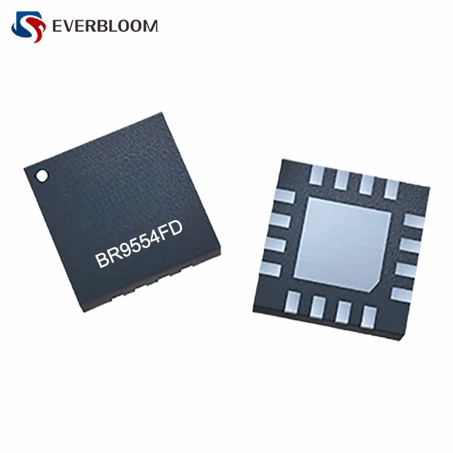

For example, some amplifiers may have a specific bias voltage that gives the best performance in terms of gain and linearity. The datasheet might also provide graphs or tables that show how the amplifier's performance changes with different bias voltages.
Step 2: Choose the Right Biasing Method
There are several ways to bias an RF Driver Amplifier, and the choice depends on your specific application and requirements.
Fixed Bias: This is the simplest method. In fixed bias, a constant DC voltage is applied to the amplifier. It's easy to implement, but it doesn't account for variations in the amplifier's characteristics due to temperature changes or component tolerances.
Self - Bias: Self - bias uses a combination of resistors to set the bias voltage based on the amplifier's own operating characteristics. It's more stable than fixed bias because it can compensate for some of the variations. However, it may require more components and a bit more design work.
Active Bias: Active bias uses active components like transistors or integrated circuits to control the bias voltage. This method offers the highest level of control and stability. It can adjust the bias voltage in real - time to compensate for changes in temperature, supply voltage, and other factors. But it's also the most complex and expensive method.
Step 3: Build the Biasing Circuit
Once you've chosen the biasing method, it's time to build the biasing circuit. This involves selecting the right resistors, capacitors, and other components based on the amplifier's requirements.
If you're using a fixed bias, you'll need to calculate the value of the resistor that will provide the desired bias voltage. You can use Ohm's law (V = IR) to do this. For example, if you want to apply a bias voltage of 2V to an amplifier with a quiescent current of 10mA, and the supply voltage is 5V, you can calculate the value of the resistor as follows:
The voltage drop across the resistor is (V_R=V_{supply}-V_{bias}=5V - 2V = 3V). Using Ohm's law (R=\frac{V_R}{I}=\frac{3V}{10mA}=300\Omega)
If you're using a more complex biasing method like active bias, you'll need to follow the circuit design guidelines provided in the datasheet or relevant application notes.
Step 4: Measure and Adjust
After building the biasing circuit, it's important to measure the actual bias voltage and the amplifier's performance. Use a multimeter to measure the bias voltage at the amplifier's bias terminal. Make sure it's within the recommended range specified in the datasheet.
Then, apply an input RF signal to the amplifier and measure its output. Check the gain, linearity, and other performance parameters. If the performance is not as expected, you may need to adjust the bias voltage. You can do this by changing the value of the resistors in the biasing circuit.
Special Considerations
Temperature Effects
Temperature can have a significant impact on the bias voltage and the amplifier's performance. As the temperature changes, the characteristics of the amplifier's components, such as transistors, can change. This can cause the bias voltage to shift and affect the amplifier's gain and linearity.
To compensate for temperature effects, you can use temperature - compensated biasing circuits or choose amplifiers that are designed to be less sensitive to temperature changes.
Noise Considerations
In some applications, noise is a major concern. The biasing circuit can introduce noise into the amplifier's output. To minimize noise, use low - noise components in the biasing circuit and keep the circuit layout as clean as possible. Avoid running RF and DC lines close to each other, as this can cause interference.
Related Products
If you're looking for other types of RF amplifiers, we also offer High Linearity Low Noise Amplifier and Low Phase Noise Amplifier. These amplifiers have their own unique characteristics and are suitable for different applications.
Conclusion
Setting the bias voltage of an RF Driver Amplifier is a crucial step in ensuring its optimal performance. By understanding the amplifier's datasheet, choosing the right biasing method, building the biasing circuit correctly, and making the necessary measurements and adjustments, you can get the best out of your amplifier.
If you have any questions about setting the bias voltage or need help with choosing the right RF Driver Amplifier for your application, don't hesitate to reach out. We're here to assist you in your procurement process and ensure that you get the best solution for your needs. Let's start a conversation about your requirements and see how we can work together to achieve your goals.
References
- RF Amplifier Design Handbook
- Application Notes from RF Amplifier Manufacturers